Wednesday, December 29, 2010

The Future Is Now!


Recently, we (the Western World) had a wintertime holiday season (take your pick of celebrations and spiritual affiliations) that traditionally includes the exchanging of gifts.  Which presents a bit of a challenge during that gift, buying / wrapping / giving time of the year.   We (Lisa and I), being the combination of two adult households, squeezed into half a house (900 feet ^2), have few unmet needs and even less room for non-essentials.  Which means, for instance, no more furniture or superfluous kitchen appliances.

One morning, at the fire station, I was leafing through newspaper advertisement inserts (which I RARELY do), thinking about the gift dilemma, when destiny brought me to a page in the Target flyer.  "Buy one, get two Roombas." Cue parting clouds, shaft of heavenly light, and choir of angels (or whatever - it's just a metaphor). 

I've been thinking about getting a robot vacuum cleaner ever since I first heard about the Roomba.  On one hand, my wife, Lisa, is a practical lass, and it's hard to sell her on gratuitous technology.  I had to exert considerable charm to get a microwave in the kitchen (but now it's indispensable).  But, on the other hand, what a perfect application for the domestic robot: a mindless dirty task.  A robot doesn't get bored, have anything better to do, or argue.  How can a gift that promises to clean the house and actually do the work not be appreciated?  And I'd get two, one to use, and one to hack. 

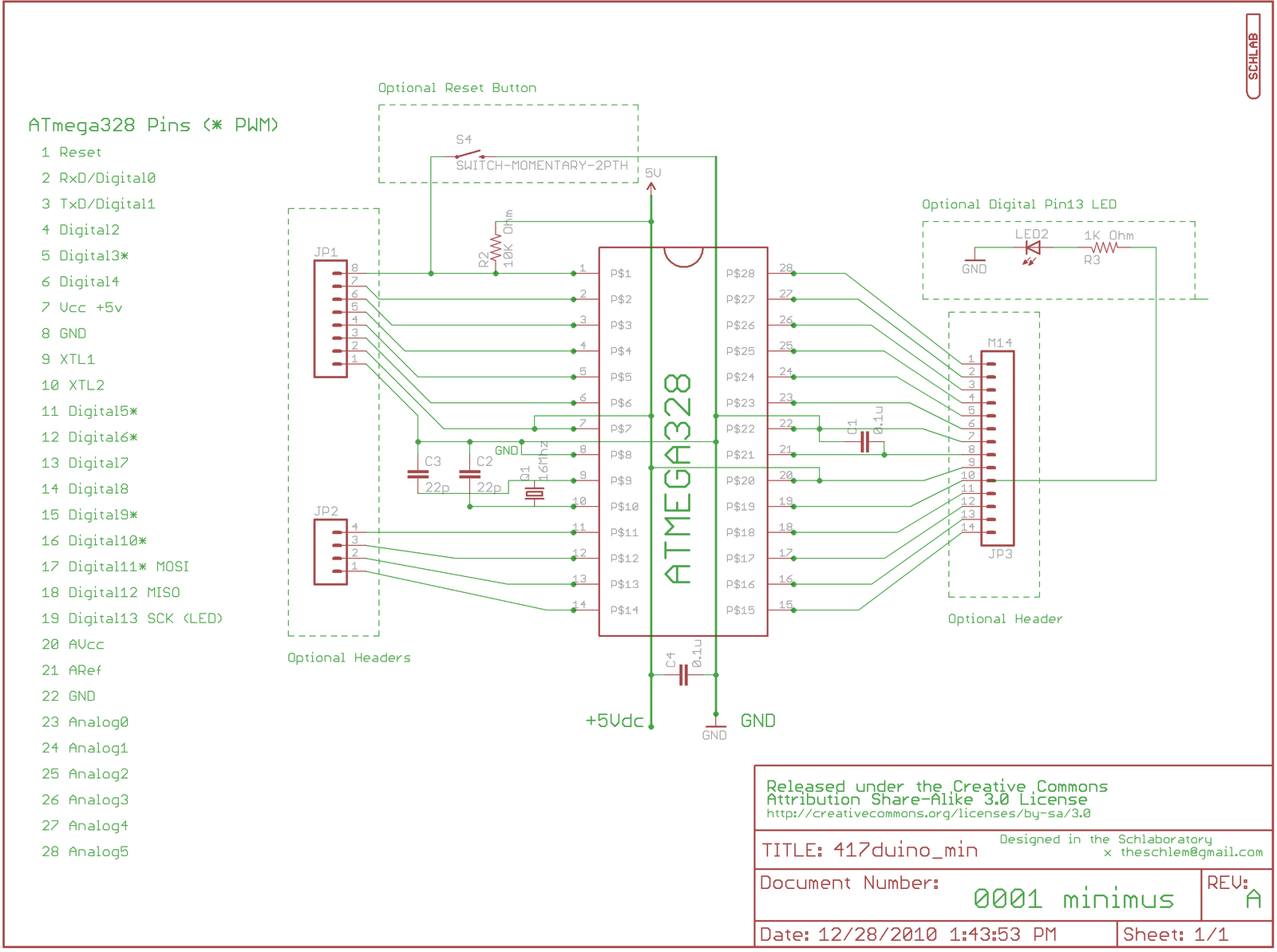
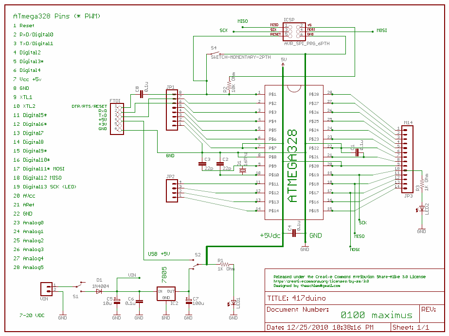
The Target offer was for a Roomba model 530 and model 400  for $299.99, a pretty good deal.  What really excited me was that the maker of Roomba, iRobot, has made their robots hacker-friendly by exposing functionality via a serial port.  The Roomba Open Interface provides access to the Roomba's sensor's and actuators through a serial communication protocol. A computer can be used to control the Roomba, either with a mini-din 7 cable tether, or wirelessly, using Bluetooth.  I intend to build an interface cable to connect a 417duino to the Roomba serial port, and exert control over function and scheduling, the 417roombino.
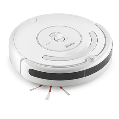
The 530 came with a charging station (a "dock") and a couple of virtual walls that could be used to keep the robot out of certain areas, or away from potential hazards.  A spare filter and cleaning tool for the spinning brush bar was included as well.  The 400 came with a plug-in charger (but there are docking station contacts on the bottom of the robot), three spare filters, and a different cleaning tool. Both robots have removable debris bins at the rear, where large particles are swept into one box, and finer particles are vacuumed into another (filtered) box.  Notably, the manual stresses the importance of cleaning and maintenance, and complete replacement parts are available from iRobot and other vendors.

How do they clean?  They suck.  No, really, they suck, and brush, and bump, and spin, and dance under and around the furniture, and into the corners, and all the little nooks and crannies.  We try to keep a clean house, but the acquisition of a Scottish Terrier last year has compromised that goal.  The first time we ran the 530, we stopped it half way through the cleaning cycle and checked the dirt bin.  We were shocked to find a thick mat of felted dog (and human) hair in the sweeper bin, and another mat of dirt, dust, and hair in the vacuum bin.  We cleaned out similar masses of debris twice more that night.  We've used the robots to vacuum seven or eight times so far, and we have had similar results every time.  The rotating brushes and sweepers get wrapped in hair and grunge, making the cleaning tools absolutely necessary.  I intend to take very good care of my robots and use them for a long time.

The differences between  the two robots are significant.  The 530 ("Dirty Gertie") is smarter in how it navigates a crowded room, slowing down as it approaches an obstacle, only nudging it gently to confirm its existence.  The 400 ("Fun Gus") just bumps into everything full speed ahead.  Gertie is quieter and seems to finesse around carpets and loose objects on the floor with more grace, while Gus occasionally gets under the rug or stuck beneath furniture.  Gertie also seems to have a little more smarts when it comes to navigating farther afield, only to find her way back to the docking station when her battery runs low.  Gus is slower to find his way out of a room, and just stops when his battery is flat with a musical "Uh-Oh".  They definitely have personalities, in the same way that new pets unfold once you bring them home.  I look forward to working and playing with them in the future. 

Dirty Gertie bumbling about the multipurpose room.

Tuesday, December 28, 2010

417duino Schematics

The 417duino Arduino-compatible is intended to be assembled from off-the-shelf components, in a variety of configurations for maximum versatility and economy.

0001 minimus
Rock-bottom basic support for a pre-programmed ATmega328 microcontroller, for use with appropriate regulated power supply.  Intended for least-expensive embedded applications.  Options: Indicating LEDs, Reset switch, headers for I/O pins (soldered connections recommended for embedded applications).


0010 medius
On-board regulated 5V power supply for pre-programmed ATmega328 microcontroller.  Intended for  embedded applications. Options: Indicating LEDs, Reset switch, headers for I/O pins (soldered connections recommended for embedded applications).


0011 magnus
On-board regulated 5V power supply, FDTI USB-Serial programming interface, Reset switch, Indicating LEDs, headers for I/O pins .  Intended for rapid prototyping, educational applications. 


0100 maximus
On-board regulated 5V power supply, FDTI USB-Serial programming interface, Reset switch, Indicating LEDs, headers for I/O pins .  Intended for rapid prototyping, educational applications, custom bootloader / ICSP programming and development. 

417duino Blinky Test


True, it's not very dynamic; it just blinks.  But it is a glorious proof of concept.  Green LED is power indicator (nominal 6V from 4 x 1.5 AA's), yellow attached to Arduino Pin13.

Using the USB BUB Board from Modern Device to reprogram the ATmega328 chip I bought from Sparkfun, I replaced an LED fader program with one that simply blinks at a constant rate.  Additionally, the 5V supply from the USB connection will power the board - must be careful not to have more than one power supply.  A SPDT switch on the power into the circuit solves this problem nicely.

This is a 417duino mashup - no on-board regulated power supply, but has the FTDI pin header, and Pin13 LED.  Initially, I assembled it with the wrong size capacitors on the crystal (22uF instead of 22pF - DOH! That's an order of magnitude error)  Didn't work -  big surprise.  Didn't brick it either, as evidenced by that beautiful blinking yellow LED.

Saturday, December 25, 2010

First Version 417duino Schematic

This is the full-feature schematic for 417duino, designed for Radio Shack PC board 276-150 (417 holes - get it?). Power supply, ICSP, FTDI are all optional modules, depending on desired functionality.


Click for larger, printable PNG format image.

This image was created in EAGLE 5.10.0 Light PCB design software.  I used a trial and error and error methodology to generate this schematic.  I make no claims of expertise with EAGLE, and there are decided errors that will not translate to a circuit board design.  While I consider this to be a trivial issue (this circuit is intended for a generic prototyping PC board, and have no intention of creating yet another Arduino-compatible circuit board), I reserve the right to modify and improve all documents relating to the 417duino. 

The 417duino Arduino-compatible is intended to be assembled from off-the-shelf components, in a variety of configurations for maximum versatility and economy.

0001 minimus
Rock-bottom basic support for a pre-programmed ATmega328 microcontroller, for use with appropriate regulated power supply.  Intended for least-expensive embedded applications.  Options: Indicating LEDs, Reset switch, headers for I/O pins (soldered connections recommended for embedded applications).

0010 medius
On-board regulated 5V power supply for pre-programmed ATmega328 microcontroller.  Intended for  embedded applications. Options: Indicating LEDs, Reset switch, headers for I/O pins (soldered connections recommended for embedded applications).

0011 magnus
On-board regulated 5V power supply, FDTI USB-Serial programming interface, Reset switch, Indicating LEDs, headers for I/O pins .  Intended for rapid prototyping, educational applications. 

0100 maximus
On-board regulated 5V power supply, FDTI USB-Serial programming interface, Reset switch, Indicating LEDs, headers for I/O pins .  Intended for rapid prototyping, educational applications, custom bootloader / ICSP programming and development. 

417Protoshield
The 276-150 PC board is too narrow to connect with the pin headers on Arduino-compatible shields, but an inexpensive shield can easily be assembled from another (that's right!) 276-150 PC board.

Plans and detailed instructions coming soon!

Creative Commons License
417duino by http://schlaboratory.blogspot.com/ is licensed under a Creative Commons Attribution-ShareAlike 3.0 Unported License.
Based on a work at http://www.arduino.cc/.

Friday, December 10, 2010

Four-One-Seven

I love Radio Shack.  Maybe not as much as I used to, but still, I'm very fond of the store.  When I was a kid, when asking for my battery-of-the-month, the polyester-clad Radio Shack salesman would happily give me a thick catalog from the stack behind the counter.  I would spend hours poring through the gossamer pages, examining everything, from resistors to a MOOG synthesizer IC (Which I bought, but never built anything with - I'd love to find another).  True to their name, they sold CB radios, shortwave radios, weather radios, and HAM equipment. 

In high school, I took an electronics class from two math teachers who also taught computer science.  Sadler and Crandell were like a midget wrestling tag team, gleefully alternating between the duties of instruction and running labs.  I enjoyed the class immensely and to pass, I was required to assemble some kind of circuit.  Mr. Crandell preferred a finished product, inside a project case of some sort with integral power and all necessary control and indication hardware.  Kits were acceptable, but I chose to make mine from scratch. 

Finding electronic circuits to construct was a vastly different process in pre-Internet 1979.  I found a circuit for a light activated alarm in a library book, imagining it to be installed inside a dark locker, triggered by some unsuspecting interloper opening the door.   I think I saw a tear of joy in the corner of Mr.Crandell's eye when I asked him to help me with etching a printed circuit board.  The circuit wasn't very complicated, and the circuit board only needed about six components.  I was horrible at soldering, and I ruined the board I had made, delaminating the conductive traces from the board matrix, a murder victim of excessive heat.  Radio Shack to the rescue.

One of the frequently-eyeballed items in the phonebook catalog was a general-purpose prototyping board, about two by three inches.  It was designed around the Dual Inline Package (DIP) integrated circuits ("computer chips") that had been developed in the sixties.  Thanks to Moore's Law, ever more complex circuits could be squeezed into ever smaller chips, and the right circuit board made working with the chips trivial.  As much as I wanted to build a computer (or a synthesizer!), I had to spend some time with the basics first.  My alarm circuit was very simple, and I really just needed some way to mount and connect the components.  Item 276-150 would fit the bill just fine. 

An aluminum box (from Radio Shack) housed the alarm, which used a CdS (Cadmium Sulfide) light sensitive cell to trigger the alarm, and mercury switches to turn it off.  There were no external controls and it could only be turned off by orienting it in a certain non-obvious way.  It was kinda cool. 

I'm reminded of my high school light alarm project because I have been building an Arduino-derived circuit on the trusty 276-150 general purpose printed circuit board.  An important part of my open source project is documenting the circuit and how it is assembled.  Developers of Arduino-compatible platforms must release a schematic and a CAD drawing of the circuit board .  The CAD program frequently used for this is an amazingly capable (and inscrutable) suite of software tools.  Once the schematic has been designed, an intelligent process generates as much or as little of the resulting printed circuit board as the designer / engineer desires. 
I'm kind of going about this process in reverse - I'm starting with an existing PC board and imposing it upon an Arduino-compatible circuit.  This circuit board is literally available in every Radio Shack, in every strip mall, everywhere.   If you buy the lovely teal Arduino board from the Italians, you'll pay about $30 (plus shipping - you can't simply run down the street to a corner store to buy Arduino).  If you buy a kit, you'll be out about half that.  My hope is that you can build my version for $6-8, depending on what you need to buy, and what features you want.  I am essentially  writing a recipe for building my vision of the Arduino-compatible.  With an open source distribution, just like as in  the kitchen, you, the user, can follow the recipe slavishly, borrow ideas from it, or evolve it into your own personal vision.

My goal for this riff on the Arduino motif is to make a microcontroller from locally-sourced (or scavenged) components as much as possible.  The user can opt for absolute minimal support for the ATmega368 chip, on-board regulated power supply, a variety of interfaces, and even a "shield" ( a "daughterboard" that stacks on top of the controller) for custom development.   Lacking the skills to use the CAD software (yet), I am working on distribution documents that describe the circuit, show assembly on the PC board, and I'm doing it all in Microsoft Paint -  that freebie drawing program that comes with Windows.  In the process, I have become intimately acquainted with the 276-150. 

The 276-150 general purpose printed circuit board measures 1.875 inches by 2.875 inches.  A single-sided PC board, there is a printed mask on top that diagrams the copper foil pads underneath.  A mounting hole in each corner allows the business-like use of standoffs to securely mount the finished circuit. Twenty five rows of holes intersect seventeen columns spaced 0.01 inch apart.  One side of the DIP pattern has three columns of discreet, unconnected pads, while opposite, there are only two columns.  The asymmetry slightly offends my OCD, but I leverage the extra room for the on-board regulated five volt power supply.  In all, there are 417 holes in the board.

I am drawing inspiration and direction from several different sources (to be acknowledged at release), and coming up with a name for my Arduino-compatible project was a significant creative challenge.  I settled on 417duino, to honor the noble phenolic rectangle that saved my grade in high school. 

Two bucks at a Radio Shack near you.


Creative Commons License
417duino by theschlem@gmail.com is licensed under a Creative Commons Attribution-ShareAlike 3.0 Unported License.
Based on a work at www.arduino.cc.

Tuesday, December 7, 2010

LAB RAT

I admit that I am a little bit, a tad, a trifle... lazy.

I say this because of a spelling error. A spelling error that zings around my obsessive compulsive mind like a shithouse fly. I wanted a clever name for this blog. I wanted "Schlab" (Schlem Lab - get it?) No dice. In a sleep-deprived state, I typed in the text box, and mispelled, my second choice: lab-O-ratory. As in every creepy Mad Doktor movie ever made: "I vill be in mein lab-OR-a-tory!"

Ah so. On one hand, Schlaboratory is an entirely madeup word. So is Schlabratory. They are equally improbable. The former is a clever riff on the word for "technical learning environment, full of much discovery and adventure". The latter is bone-headed oafishness.

Back to lazy... I could copy the few posts in this new blog to newer blog with the right name.

Never mind. I did just that. Schlabratory is dead, long live Schlaboratory!

Freeduino Diary

A year or more ago, I built a series of small, scratch-built Lego robots. It was something I had always wanted to do. The Genius Triangle (Time, Resources, Interest) snapped together and the first soldier in my robot army was born.

I had banged around on the original Lego Mindstorms robot kit ten years ago, and it was all right, but I wanted the potential for more than five sensors and three motors. Programming in the graphical IDE didn't work very well for me either - even though I always thought I was a visual kind of guy.

I decided to get some Parallax Basic Stamp microcontrollers and figure out how they worked. For a brief while, eBay was rich with miscellaneous Basic Stamps, and my minions multiplied. I built everything on the robots from scratch, without plans or kits. I dusted off my soldering skills and built a number of switched 5V regulated power supplies. I made brackets that interfaced Legos to Futaba servo motors. It was fun, it was satisfying. Every robot was an improved iteration of the previous, primarily focused on improving the Lego mechanics.

Basic Stamps are well designed and well supported. A simple Google search will deliver a rich encyclopedia of PBASIC code. But my disinterest was fueled by two factors: They're hugely proprietary, and relatively expensive. Nobody make a Basic Stamp clone, and they cost vastly more than a standalone microprocessor. It reminds me of the Apple Macintosh product line.

I've been thinking a great deal about Open Source lately. I believe that multiple vendors supplying an open source (or licensed source) product benefit the consumer more than a corporate choke-hold on intellectual property. The people at Parallax (and Apple) are very smart, but I feel they're focused more on controlling production than ubiquity. At one extreme, that strategy leads to cartel pricing and can be very profitable when you are good at manufacturing something people desperately want. On the other hand, Microsoft built its empire on ubiquity driven by software and content.

The Arduino is an open source microcontroller that is inexpensive and available in a wide variety of configurations. I recently built my first Arduino-compatible (a "Freeduino" design called the MaxSerial), having bought the kit months ago, on eBay, with an eye to building the next generation Schlembot around it.

This is exactly what I am looking for in my future microcontroller projects. Even a full-featured unit from one of the many companies that make compatible hardware is about half the price ($25) of a bottom-spec Basic Stamp. A kit can be had for about half of that ($12.50). You can even build one from scratch, with another halving in price ($7.00).

I always find that one interest fuel other interests, and thus I've been designing an Arduino-compatible circuit to push the limits of cheap, versatile, utility. The Creative Commons license on Arduino-compatible hardware allows you to adapt, modify, and customize hardware or software for your own purposes, with the proviso that you make the derived product available with the same license. The basic circuit has been fully developed for years, with subsequent variations by different designers (serial communications, USB, breadboard compatible, minimal, maximal...).

I am porting the Arduino circuit to a general purpose prototyping board, sold by Radio Shack for years. I used the 276-150 for high school science projects. Any description of this PC board touts its precisely drilled 417 holes. There is not a lot of creative design in this endeavor, but the goal is make a "recipe" for assembling a homebrew Arduino-compatible from readily available electronic components. Actually, naming the design presented the biggest challenges to my creativity. After a couple of beta monikers, I settled on 417DUINO (after the number of holes in the jaunty little PC board).

The final version will have an on-board regulated power supply, USBTTL programming, an ICSP programmer connection, and be stackable with 276-150-based protoboards.

Many open source electronic products are designed with a (printed circuit board design) CAD tool called EagleCAD, but I've been satisfying my obligation to document the design of 417DUINO in your basic bitmap editor, Windows Paint. I want to learn EagleCAD, to make a mask for the 276-150 PC board, but that can wait. For now.


Creative Commons License
417duino by theschlem@gmail.com is licensed under a Creative Commons Attribution-ShareAlike 3.0 Unported License.
Based on a work at www.arduino.cc.

Hello World

Hi geeks. You know who you are; you probably get the little joke in the title of this posting. This blog is about the geeking, hacking, thinking, and creating in which I engage. I'm a project guy; I'm always working on some kind of project. This is a forum where I can share intricate details that don't scale to Facebook. It's also a vehicle to share my enthusiasms and perspective on the things that excite me, through a medium of self-publication.

This is now my "other blog". You can read Schlem's Short Report here. I started THAT blog to share some of the crazy experiences I have as a firefighter, but it has evolved into a biographical project. It was always about writing stories - something I enjoy - but haven't had much inspiration of late. I'm kinda sick of my internal voice, and the way it starts to grate when I am trying to craft a narrative. Hopefully, THIS blog will give me something to write about that isn't quite so navel-gazingly introspective. ...And maybe the muse will patch in the wiring in my brain to loose the torrent of things I'd like to write about. Stay tuned.

Please feel free to leave your comments!

Thanks for reading - the Schlem